
Sonoff S20 (ESP8266) wireless smart switch flash memory upgrade
Published Aug 29, 2019
Warning
Absolutely no warranty that the things here will work and I discourage to follow these steps since high voltage and extremely hot soldering machines are involved. Use it on your own risk!
Background
So first of all some info why this post created.
When I’m not writing software then I like playing with hardware.
I’ve created several projects in the home automation area and now wanted to extend my system.
Namely I wanted to turn cameras on/off in my home while I’m away in a secure way.
Yeah, security is quite important to me. There are several devices on the market
which connect to a server but don’t know where exactly and does? some kind of authentication.
Personally I don’t trust them. I’ve reversed couple of such products and found quite
interesting things. Not mentioning all the problems but it’s quite common issue that the
authentication key is somehow hardcoded on the device (if authenticates).
In the worst case I’ve found the same key on all devices :)
Well, yeah I haven’t bought the most expensive products ![]()
So to achive this I’ve decided to buy a smart socket which:
- is cheap
- hackable (to connect to my server)
- can provide encryption + authentication
After some exploration I’ve found the Sonoff S20 smart plug:

- It was about $9.42
- There is a Sonoff-Tasmota project which can be installed to the device
- Sonoff-Tasmota contains (amongst others) MQTT + SSL
There are several forums/posts where such tutorials partially described but all of them miss the debugging part (what if not working). Since I’ve faced several issues thought it worth to make this post which contains:
- exact hardware part numbers
- exact software versions
- problems and solutions
Hardware
After opening the cover one see 4 holes on the PCB. Headers has to be installed for programming. See the pinout on the picture.
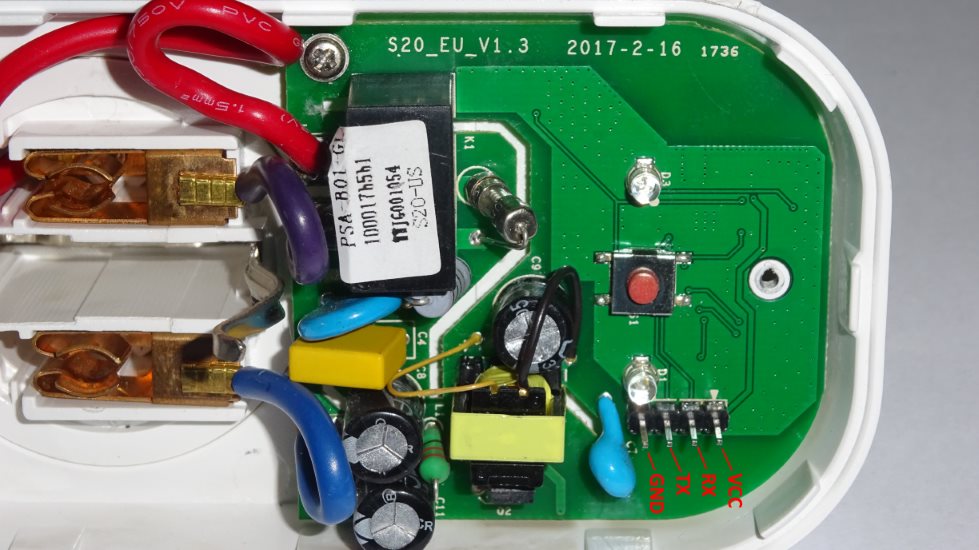
The original flash(XTX PN25F08B 1725XDG) is only 1MB which is not enough to compile Sonoff-Tasmota with Webserver + SSL + MQTT (Over the air upgrade also fails). So this had to be changed with a bigger one. I’ve chosen WINBOND W25Q32FVSIG 1416 which is a 4MB flash.

Here came the first problem during desoldering. I thought I’m doing this hobby for really long time and advanced enough to skip to bring up the hot air gun (I was damn lazy)
and able to desolder it with normal hot iron. The main problem was that I’ve applied a little bit more force than needed and the result can be seen here ![]()
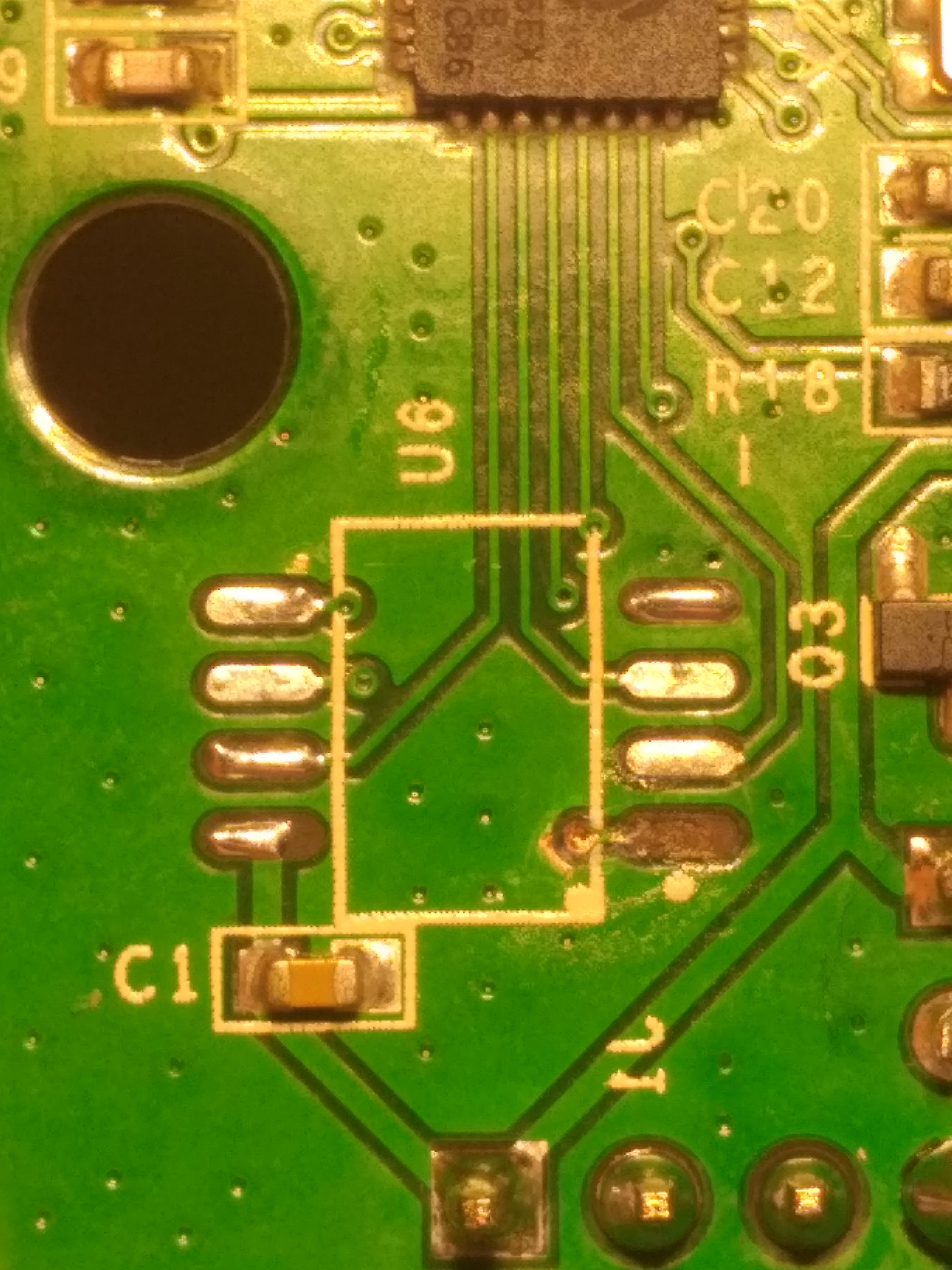
It can be definitely done with hot iron but needs some patience (I’ve ordered only 2 swithes so brought up the air gun because didn’t want to make further risk) ![]() The WINBOND chip is bigger in physical size so the legs has to be adjusted a bit. The changed board looks like this:
The WINBOND chip is bigger in physical size so the legs has to be adjusted a bit. The changed board looks like this:

The soldering is a big ugly but it will do ![]()
Software
So now need the Sonoff-Tasmota firmware which can be burned into the hardware. The source code can be found in the following link: https://github.com/arendst/Sonoff-Tasmota/
Here there are 2 ways to get the binary:
- Download pre-compiled version from the releases section
- Compile the source by ourself
Since MQTT and SSL is not a pre-compiled feature source code has to be compiled.
So I’ve checked out the code and used the latest development branch to compile. I was standing at commit SHA f5646d6bbe88d2ea59118ab786901dbcace39aad. Before compile the code couple modifications in sonoff/my_user_config.h has to be made. Namely the following 2 compile flags has to be enabled:
- USE_MQTT_TLS
- USE_MQTT_TLS_CA_CERT
When the file modified nothing else left just to compile the project. To do that PlatformIO has to be installed:
e:\projects\Sonoff-Tasmota>"pio --version"
PlatformIO, version 3.5.4

e:\projects\Sonoff-Tasmota>"pio run -e sonoff"
...
At the end of compilation the following file must be created:
e:\projects\Sonoff-Tasmota\.pioenvs\sonoff>"dir firmware.bin"
 Volume in drive E is Storage
 Volume Serial Number is XXXX-XXXX

 Directory of e:\projects\Sonoff-Tasmota\.pioenvs\sonoff

2019-08-29  21:22 PM           603,440 firmware.bin
               1 File(s)        603,440 bytes
               0 Dir(s)  XXX bytes free
Flash
There are multiple ways to flash it:
- Using esptool
- Using arduino
I’ve chosen the first one because I think the arduino stuff is complicated (roughly the same cabling but installing all the tools is hell). In order to connect to the board one need a 3.3V USB to TTL Serial Adapter, I’ve bought an FTD1232 (€2.14):

and here is the cabling:
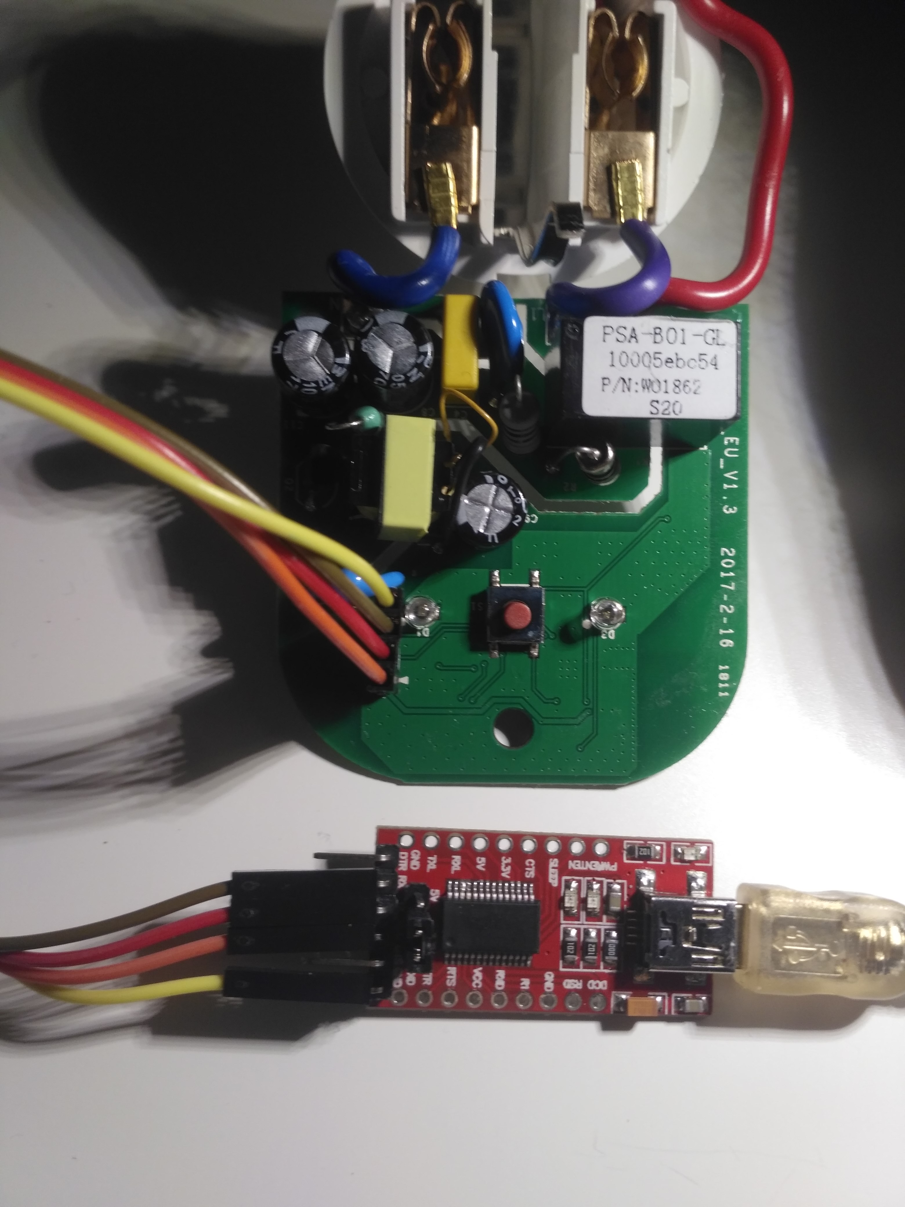
Please notice that the FTD1232 board supports 3.3V and 5V as well and now 3.3V must be chosen (the jumper next to the output pins). After it’s connected esptool has to be cloned and used.
First of all one need to check that the upgrade was successful and the flash memory responding:
e:\projects\esptool>"esptool.py --port COM3 flash_id"
...
Here I’ve faced several problems:
- The flash reading was timing out => The board circuit was broken because I’ve used hot iron with more power than needed (see the picture above).
- With a new board the flash reading was timing out => I’ve desoldered the chip, logic analyzer and turned out was dead initially (it’s a cheap stuff and couple of pieces are initially dead).
- Until now I didn’t mention the esptool version and for reason. The latest 2.7 version provided constant timeout when tried to read the dead/badly soldered chips. This kinda makes sense because the chip was dead or not connected. At that stage I’ve downgraded to 2.4.1 which connected but read ID 0xFF back. This was kinda the breakthrough. Googling the problem somebody written the ID 0xFF means the chip is not responding (I’ve done so many things that I didn’t know whether I’ve killed the whole board or not). So this is not really a problem just lead me to the right direction. After the soldering fixed + the chip was functioning both versions are able to communicate properly.
Finally the board can be flashed properly (the button on the sonoff must be pressed while the serial adapter plugged, this puts the board into flash mode):
e:\projects\esptool>"esptool.py --port COM3 write_flash -fs 4MB -fm dout 0x0 firmware.bin"
...